Project 1
Practice: Sport Palace
Dome Geometry
he dome of this building is composed of
two curves, forming a synclastic surface. The primary dome features two
downward-curving arches that are perpendicular to each other. However, within
each grid or segment of this main surface, the panels are made up of smaller
surfaces resembling hyperbolic paraboloids. These internal components are
formed by one upward and one downward curve, which gives the structure its
complex form. This geometric configuration was a key factor in my decision to
model this building in Revit.
Figure 1. Sketch of the grid analysis using the deformation method (Damy Rios, 1968)

Step-by-Step Revit Modeling Workflow for The Sports Palace
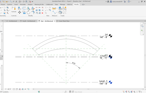
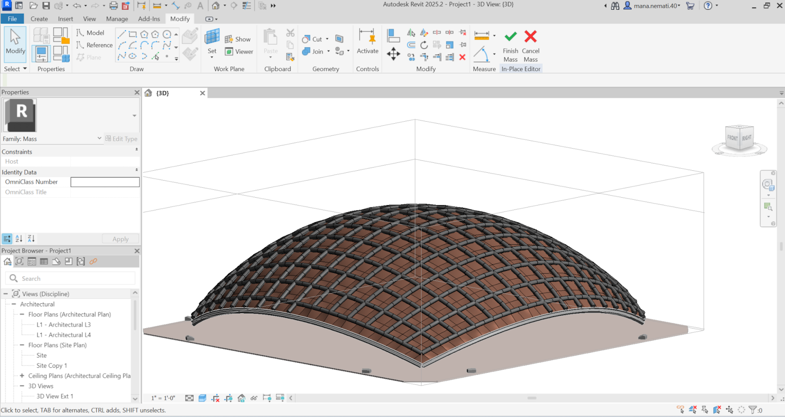
For modeling the dome, Employing Mass In Place command, I first
established the boundary based on the angle from the center of the spherical
surface, according to the provided drawings. I defined the boundary along two
perpendicular work planes. The intersection of these two work planes formed the
main shape of the roof.
At this stage, I needed to define an
Adaptive Component, so I created a
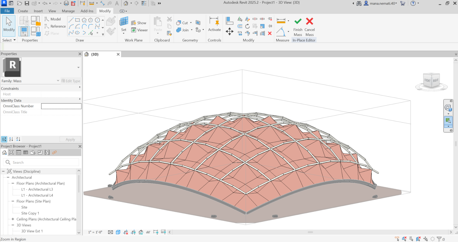
Curtain Panel Adaptive Component Family. I began modeling both the metal
frames that are placed on top and the panels, which needed to be parabolic and
created as surfaces. One major challenge I encountered
was that since the panels were curved, they didn’t align properly along the
Z-axis when placed on the surface. I eventually realized that instead of using
Ref Planes, I needed to use Ref Points with a specific offset applied to the
top adaptive points to ensure correct placement and alignment of the panels.
Finally, I defined several parameters to
control the model. These included parameters for the visibility of each element separately, allowing individual control
over the components. Additionally, I created parameters for adjusting the thickness of the elements, their height, and the material properties. These parameters ensured flexibility in
modifying the model as needed for different design or construction
requirements.
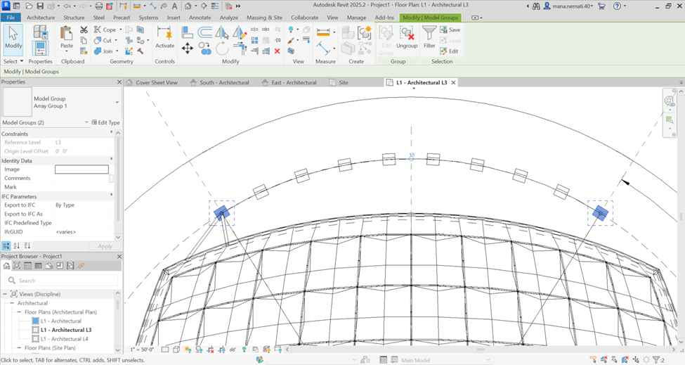
In the next stage, after the shell form
was established, I modeled the side
columns and the column bases,
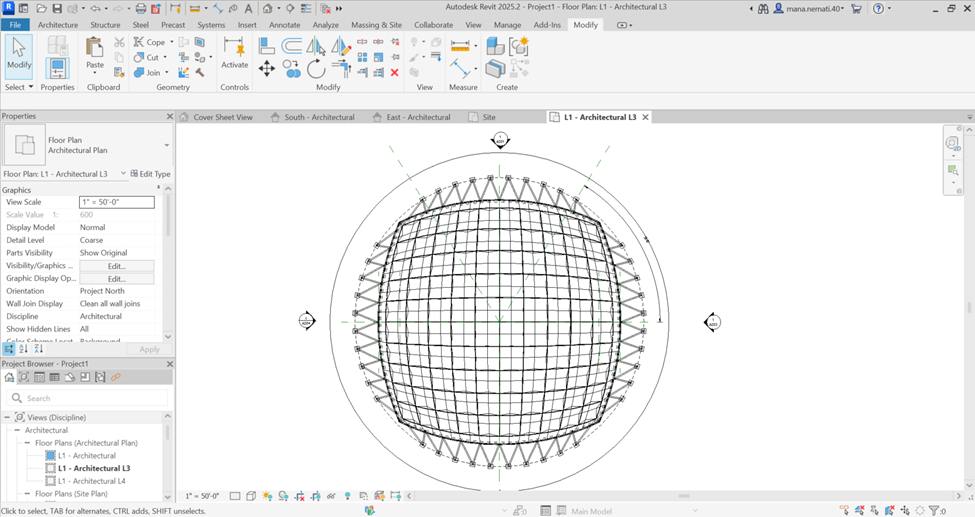
along with the remaining structural profiles. Using the Array tool, I applied a circular
angular array, distributing the structural elements around the entire
perimeter of the dome. This allowed me to connect all the structural components
to the roof uniformly.
For the external walls, due to their
specific form, I had to create the walls using the Component tool. I built a new family in the Wall category, then imported it and placed it accordingly to match
the desired wall shapes.
For the interior design, considering that
the building functions as an auditorium, I designed the circular seating arrangement. To achieve this, I manipulated a Railing component where all the seats
were defined within a single railing component. Instead of using the default
railing profile, I replaced it with a stepped
profile that defined the seating layout. This approach allowed me to place
the auditorium seats by simply drawing a railing line along the desired path,
and the seats would automatically follow that line.
Finally, the remaining interior details,
including the stairs and walkways
between paths, were added, and the internal layout and elements were fully
grid-aligned. Since the file size became large, I divided the project into two
separate files—one for the exterior and one for the interior. I then used Revit Link to connect both files,
ensuring smooth coordination between the internal and external models.
AI-Generated Design Variations (Chat GPT 4o)
Parametric Envelop
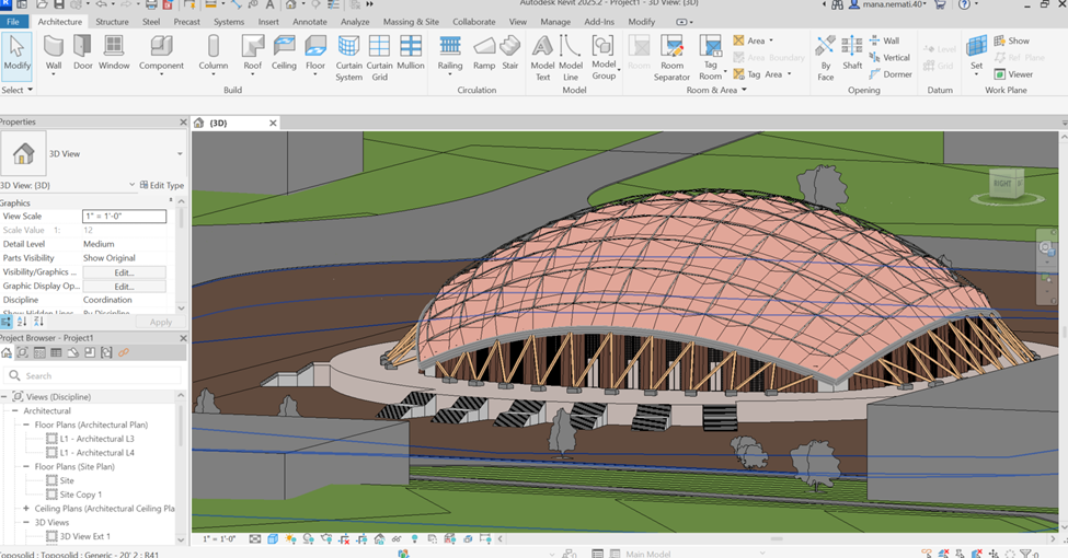
Here are four different screenshots, each showing different shapes I obtained by adjusting parameters like roof pattern, material properties, and more.












Comments
Post a Comment